




Silage clamp design and construction require careful planning, structural engineering and effective pollution prevention. Whether a clamp is being built for a dairy farm, livestock enterprise or agricultural anaerobic digestion (AD) plant, the objective is to store forage safely, minimise avoidable crop losses and prevent silage effluent from entering land drains, groundwater or watercourses.
A poorly designed silage clamp can become an expensive liability. Cracked concrete, inadequate drainage, overloaded retaining walls or leaking effluent channels may result in serious pollution incidents, regulatory action and substantial repair costs.
This guide explains silage clamp design, construction methods, vertical and sloping walls, effluent containment, structural loading, planning and UK regulations. It includes historical examples of precast concrete clamp construction and practical recommendations for farmers, AD developers, designers and contractors.
Key Takeaways: Silage Clamp Design and Construction
- Choose the correct clamp configuration: Flat-pad, vertical-wall and sloping-wall designs have different land, engineering and operational requirements.
- Design for actual machinery loads: Modern loading shovels and compaction tractors can impose substantial lateral loads on clamp walls.
- Make the base and drainage system impermeable: Silage effluent must be collected and contained, not allowed to escape into surrounding ground.
- Assess drainage before construction: Clean surface water and contaminated silage effluent should be managed through an appropriately designed drainage system.
- Check planning requirements: Agricultural permitted development rights do not automatically apply to every silage clamp, particularly where the facility serves a commercial AD operation.
- Comply with relevant pollution controls: In England, new silage storage and substantial changes to existing installations normally require Environment Agency notification at least 14 days before construction begins.
- Plan for a long service life: Materials, construction details, inspection access and maintenance arrangements must address aggressive silage effluent and demanding operational conditions.
What Is a Silage Clamp?
A silage clamp, sometimes called a silage pit, bunker silo or silage bunker, is a facility used to store chopped forage crops while they undergo controlled fermentation under oxygen-limited conditions.
Typical materials include:
- Maize silage.
- Grass silage.
- Wholecrop cereal silage.
- Other suitable ensiled agricultural crops and forage mixtures.
The material is placed in the clamp, consolidated to expel air and covered using appropriate impermeable sheeting and sealing arrangements.
Correct ensiling encourages fermentation by suitable microorganisms, producing organic acids that help preserve the stored biomass.
Silage clamps are particularly important at agricultural biogas plants because ensiled energy crops and other suitable agricultural materials can provide a relatively consistent feedstock supply throughout the year.
For more detail on harvesting, compaction, sealing and preserving methane yield, see our separate article: Biogas Silage Management Techniques and Optimisation Strategies.

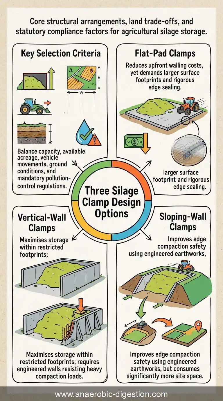
Three Main Silage Clamp Design Options
Silage clamp designers normally consider three broad arrangements:
- Flat-pad clamps without permanent retaining walls.
- Vertical-wall clamps using reinforced concrete, precast concrete or other suitably engineered retaining structures.
- Sloping-wall clamps, often constructed using engineered earthworks with an impermeable internal surface.
The correct option depends on required storage capacity, available land, ground conditions, vehicle movements, construction costs, surface water management and site-specific planning constraints.
1. Flat-Pad Silage Clamps
A flat-pad clamp consists of a suitably designed impermeable base on which silage is stored without substantial permanent retaining walls.
The absence of retaining walls can simplify the structural arrangement and reduce initial construction costs in suitable circumstances.
However, the crop must be managed to maintain stable slopes and prevent unsafe working conditions.
Potential advantages:
- Relatively straightforward construction.
- Absence of tall retaining walls.
- Potential flexibility in storage layout and access.
- Reduced investment in structural walling.
Potential disadvantages:
- A larger footprint for the same storage volume.
- More difficult consolidation and sealing at the edges.
- Potentially greater exposed surface area.
- Need for careful management of side slopes and sheeting.
- Potential difficulties maintaining safe and effective effluent collection around the stored material.
A flat pad does not remove the need for compliant containment. Where the installation is a regulated silo in England, the relevant impermeability and effluent drainage requirements still apply.
2. Vertical-Wall Silage Clamps
Vertical-wall clamps use retaining walls to contain the silage within a defined footprint.
The walls may be formed from reinforced concrete cast in situ, prestressed or reinforced precast concrete panels, or another appropriately engineered construction system.
Vertical walls can make efficient use of available land and are often attractive where storage volume must be maximised within a restricted area.
Advantages:
- Efficient use of the available footprint.
- Clearly defined storage bays.
- Potential suitability for modular precast construction.
- Relatively straightforward integration with adjacent storage bays.
- Ability to incorporate engineered access and drainage details.
Disadvantages:
- Substantial lateral loads from silage and compaction equipment.
- Potential damage from loading shovels or tractors.
- Need for properly engineered foundations and wall connections.
- Fall hazards near unprotected wall tops.
- Inspection and maintenance requirements for concrete, joints and seals.
The retaining wall must be designed for the actual imposed loads and not simply selected by height or panel thickness.
3. Sloping-Wall Silage Clamps
Sloping-wall clamps generally incorporate inclined retaining surfaces. These may use engineered earthworks behind a purpose-designed lining or facing system.
Where ground conditions and space permit, excavation and filling can sometimes be balanced to reduce imported or exported material.
A suitably designed sloping wall may allow compaction machinery to operate nearer the clamp edge while reducing some of the direct impact risks associated with vertical walls.
Advantages:
- Potentially effective compaction towards the edges.
- Reduced exposure to certain vertical-edge working hazards.
- Possible opportunities for balanced earthworks.
- Potential reduction in the structural demands placed on a free-standing vertical wall.
Disadvantages:
- Greater land take.
- Dependence on suitable ground conditions and earthworks design.
- Need for effective impermeable lining and sealed construction details.
- More complex arrangements at corners and drainage interfaces.
- Potential difficulties inspecting concealed leakage.
A sloping earth bank is not, by itself, an acceptable substitute for an impermeable silage containment structure. The complete design must meet the relevant pollution-control requirements.
Vertical vs Sloping Silage Clamp Walls: Which Is Better?
| Design consideration | Vertical wall | Sloping wall |
|---|---|---|
| Land required | Generally smaller footprint | Generally greater footprint |
| Structural loading | Substantial lateral and compaction loads | Depends on slope, backing material and structural arrangement |
| Compaction near edges | Requires careful operating procedures | May offer operational advantages |
| Construction | Precast or cast-in-situ concrete commonly used | Engineered earthworks with appropriate lining or facing |
| Ground conditions | Foundation bearing and settlement important | Earthwork stability and settlement important |
| Safety | Fall and impact hazards must be controlled | Slope stability and machine safety must be controlled |
| Drainage | Requires effective collection and sealed interfaces | Requires effective collection and impermeable construction |
These are qualitative comparisons. Neither arrangement is inherently the best solution for every site.
How to Calculate Silage Clamp Storage Capacity
The required storage volume should be established before selecting a wall system or obtaining construction quotations.
For an agricultural anaerobic digestion plant, the storage calculation should consider the annual quantity of ensiled feedstock, harvest periods, daily digester demand, expected storage losses and operational reserve requirements.
Step 1: Establish the Quantity of Silage Required
Determine the quantity to be stored in tonnes, allowing for the expected duration of storage and any relevant operational contingency.
Step 2: Establish a Realistic Bulk Density
Silage bulk density varies with crop type, dry matter content, particle size, filling method and degree of compaction.
Use a defensible density estimate based on the actual material and the proposed operating procedure. A value taken from a different crop or clamp should not automatically be applied.
Step 3: Calculate the Net Storage Volume
Net storage volume (m3) = Stored silage mass (tonnes) ÷ Assumed bulk density (tonnes/m3).
For example, consider an illustrative requirement to store 6,000 tonnes of silage at an assumed compacted density of 0.70 tonnes/m3.
The required net storage volume would be:
6,000 ÷ 0.70 = approximately 8,571 m3.
This is an example only. The density must be appropriate to the feedstock, and the calculation must allow for sloping exposed faces, usable storage height and any other geometrical restrictions.
Step 4: Assess the Clamp Geometry
For a rectangular clamp with effectively vertical sides, an initial geometric estimate is:
Gross volume = length × internal width × usable average height.
However, the net usable volume may be lower because of the clamp’s end face, operating margins, cover arrangements and actual filling profile.
Sloping-wall clamps require a geometric calculation appropriate to the cross-section.
Step 5: Confirm Operational Requirements
Storage capacity should not be maximised without considering the practical requirements of loading, consolidation, sealing and feed-out.
A clamp that is excessively wide or poorly proportioned may create avoidable difficulties with silage management.
Structural Design: Silage Loads and Modern Compaction Machinery
Structural design is one of the most important safety considerations when constructing a silage clamp.
Wall failures can create serious risks to personnel, machinery and nearby infrastructure.
Clamp retaining structures must resist the combined effects of stored silage, compaction machinery, possible impact loads, ground conditions and any relevant earth or water pressures.
BS 5502 and Silage Clamp Wall Loading
England’s Environment Agency guidance references BS 5502-22:2003+A1:2013 for silage clamp wall loading.
However, the designer must also consider the actual machinery and operational conditions expected at the site.
Large modern compaction tractors and wheeled loaders may impose loads significantly different from those assumed in older standard design examples.
It is therefore inappropriate to assume that a standard precast concrete panel will be satisfactory solely because it is described as a silage clamp wall.
The structural engineer should obtain sufficient information to assess:
- Maximum stored silage height.
- Expected silage properties and lateral loading.
- Compaction machinery operating mass and wheel loads.
- Proximity of machinery to wall edges.
- Potential accidental impact and operational surcharge loads.
- Foundation bearing capacity and settlement.
- Wall-panel connections, anchors and joints.
- Construction tolerances and long-term durability.
The designer should also assess any applicable structural standards and engineering guidance, rather than relying exclusively on older rule-of-thumb wall details.
Precast Concrete Panels
Precast concrete can offer rapid installation, factory-controlled manufacturing and consistent panel dimensions.
Nevertheless, the complete system must be designed, including foundations, panel connections, anchors, joints and any necessary restraints.
Resin anchors and other proprietary fixings require appropriate design, installation procedures and verification. They must not be treated as universally suitable without checking loads, embedment and the condition of the supporting concrete.
Cast-in-Situ Reinforced Concrete
Cast-in-situ concrete may be advantageous where site geometry, ground conditions or loading requirements make standard precast systems unsuitable.
Construction quality, reinforcement placement, concrete durability, joints and water-tightness require particular attention.
Silage Clamp Concrete: Durability and Chemical Resistance
Silage effluent is acidic and can attack vulnerable concrete surfaces.
Concrete specification should therefore consider chemical exposure, abrasion, freeze-thaw effects where relevant, traffic loading, construction joints and the intended service life.
Good performance depends on more than compressive strength alone.
Important requirements include:
- Appropriate structural concrete specification.
- Suitably controlled permeability.
- Adequate reinforcement cover.
- Correct joint details and chemical-resistant sealants.
- Appropriate curing and construction quality assurance.
- Protection against excessive abrasion from machinery.
- Regular inspection and maintenance.
Specialist coatings or linings may be appropriate in some locations, but their chemical resistance, mechanical durability and repair arrangements must be evaluated.
A lining or coating should not be assumed to compensate for deficient structural design or unacceptable cracking.
Silage Clamp Drainage and Effluent Collection
Silage effluent is a serious water pollutant. Its high concentration of biodegradable organic compounds can rapidly deplete dissolved oxygen in receiving waters, causing severe harm to aquatic ecosystems.
The prevention of effluent escape must therefore be an integral part of clamp design rather than a late addition to the civil engineering works.
Impermeable Base and Drainage Channels
In England, the SSAFO requirements for regulated silage silos include an impermeable base extending beyond the silo walls and impermeable collection channels draining to an effluent tank.
The drainage system must be designed to collect contaminated liquids without allowing leakage to the surrounding environment.
Interfaces between the base, walls, channels and tanks deserve particular attention because construction joints and penetrations can become leakage pathways.
Separating Clean and Contaminated Water
A suitable design should minimise unnecessary entry of clean water into the contaminated effluent collection system.
However, rainfall contacting silage, contaminated surfaces or affected working areas may become polluted and require containment.
Drainage design should distinguish between:
- Clean runoff from uncontaminated areas.
- Silage effluent produced during storage.
- Contaminated rainwater from exposed or dirty clamp surfaces.
- Washdown water associated with clamp operation.
The routing of water must reflect actual operating conditions, including filling, storage and feed-out.
Where diversion systems are used, they must be designed and operated to prevent accidental discharge of contaminated water.
Silage Effluent Tank Sizing in England
Environment Agency guidance specifies minimum effluent tank capacities based on silo capacity.
| Silo storage capacity | Minimum effluent tank capacity |
|---|---|
| Up to 1,500 m3 | 20 litres for each cubic metre of silo capacity |
| Above 1,500 m3 | 30 m3 plus 6.7 litres for each cubic metre above 1,500 m3 |
For example, an illustrative 3,000 m3 silo would have a minimum calculated effluent tank capacity of:
30 + (1,500 × 0.0067) = 40.05 m3.
This is the regulatory minimum calculation, not necessarily the appropriate final design capacity.
The tank must be capable of accommodating actual expected effluent flows, including relevant contaminated rainfall, peak production and any necessary operational contingency.
Additional capacity may therefore be required.
Official source: Environment Agency – Storing Silage, Slurry and Agricultural Fuel Oil.
Effluent Tank Durability
The English guidance requires above-ground effluent tanks to resist silage effluent attack for at least 20 years with maintenance.
If any part of the effluent tank is below ground, the applicable requirement is for impermeability over at least 20 years without maintenance.
The operator must be able to demonstrate that the proposed storage construction meets the relevant requirements.
Silage effluent must never be discharged directly into a watercourse or ordinary surface water drainage system.
Silage Clamp Regulations in England: 2026 Requirements
The principal regulations covering silage storage in England are the Water Resources (Control of Pollution) (Silage, Slurry and Agricultural Fuel Oil) (England) Regulations 2010, commonly referred to as SSAFO.
Current Environment Agency guidance, updated in January 2026, provides practical information about notification, construction requirements, effluent collection and the responsibilities of farm operators.
Environment Agency Notification
Operators must notify the Environment Agency at least 14 days before constructing new silage storage or making substantial changes to an existing installation.
This is notification before construction, not simply notification before the completed clamp is used.
Substantial alterations may include major structural works, relocation or changes increasing capacity. Minor routine repairs do not necessarily have the same notification requirements.
Notification is separate from any planning permission or other consent that may be necessary.
Use the Environment Agency’s online notification guidance for new or substantially altered stores.
Distance from Watercourses
Silage must not be made or stored within 10 metres of inland or coastal waters under the general English rules.
Further restrictions apply to certain field silage arrangements near protected water supply sources.
Site-specific conditions may justify greater separation distances or additional containment measures.
Existing Older Silage Clamps
Certain installations constructed before March 1991, or constructed under qualifying contracts completed within the historic transitional period, may benefit from exemptions from requirements for new stores.
However, those exemptions may cease to apply following substantial modifications, and the Environment Agency can require improvements where an installation presents a significant pollution risk.
An old clamp is therefore not automatically acceptable merely because it predates the current regulations.
Planning Permission and Permitted Development
Planning control is separate from SSAFO compliance.
Some agricultural development may benefit from permitted development rights, subject to the relevant land area, siting, dimensions, use and other conditions.
However, it would be incorrect to assume that every clamp below 465 m2 is automatically permitted, or that every clamp above that area necessarily requires a conventional full planning application.
The proposed development must be assessed under the applicable planning legislation and current local circumstances.
In particular, a clamp primarily serving a commercial anaerobic digestion operation may raise different land-use considerations from a conventional agricultural forage store.
Planning advice should be obtained from the local planning authority before major construction expenditure is committed.
Regulatory Requirements in Wales, Scotland and Northern Ireland
The legal requirements vary across the United Kingdom.
In Wales, silage storage is subject to Welsh pollution-control requirements, with Natural Resources Wales responsible for the relevant regulatory oversight. The 2026 Welsh guidance confirms a 14-day notification requirement for new or substantially enlarged silage clamps.
Scotland and Northern Ireland have separate environmental regulatory arrangements and guidance. Operators should consult SEPA or the Northern Ireland Environment Agency, as appropriate, for the relevant requirements.
Do not assume that English standards, notification arrangements or planning thresholds apply without modification elsewhere in the UK.
Welsh reference: Welsh Government – Cross Compliance: Water Protection 2026.
Planning and Constructing a New Silage Clamp
A reliable silage clamp development process should proceed through a logical engineering sequence.
1. Define the Storage Requirement
Establish the annual quantities and types of crop to be stored, required reserve capacity, harvesting arrangements and feed-out rate.
2. Assess Site Suitability
Review ground levels, access, proximity to watercourses, ground conditions, available area, land drainage and any protected environmental features.
3. Undertake Appropriate Ground Investigation
Foundation design may require investigation of bearing capacity, groundwater, made ground, compressibility and settlement.
Sloping-wall options may require assessment of earthwork stability and suitable construction materials.
4. Select the Structural Arrangement
Compare flat-pad, vertical-wall and sloping-wall options using whole-life cost, storage efficiency, drainage, construction complexity and operational safety.
5. Design Drainage and Effluent Storage
Confirm impermeable containment, drainage falls, effluent tank capacity, peak flow arrangements, inspection access and the separation of clean and contaminated water.
6. Confirm Planning and Environmental Requirements
Obtain necessary planning advice, submit the appropriate environmental notifications and address any other applicable authorisations.
7. Prepare Construction Specifications
Specify structural elements, foundation details, concrete durability, impermeable surfacing, joint sealants, drainage channels, tanks and quality assurance requirements.
8. Inspect and Test Before Use
Construction inspection should confirm that the completed structure follows the approved design.
Particular attention should be given to joints, drainage falls, connections, tank integrity and defects capable of causing leakage.
Historical Case Study: JP Concrete at Frogmary Green Farm, Somerset
One of the original examples in this article described a silage clamp constructed for an agricultural anaerobic digestion development at Frogmary Green Farm in Somerset.
The case study was originally reported in November 2018 and has been retained here as a historical example of specialist precast concrete construction.
Project Background
The development involved JP Concrete working with David Civil Engineering to provide silage storage for the farm-based AD operation associated with Sustainable Energy Generation.
The contemporary project account described a farm of approximately 320 hectares producing a range of agricultural crops, including grass, cereals, maize and fodder beet.
It reported the supply and installation of 73 precast concrete panels, identified as 316/250 AGRI L panels.
The panels formed approximately 182.5 metres of retaining wall.
Construction Arrangement
The original account described the concrete panels being resin-anchored to a reinforced concrete foundation constructed by David Civil Engineering, with an asphalt surfacing arrangement installed as part of the completed facility.
Particular attention was given to the quality and finish of the concrete surfaces because of concerns about the aggressive nature of silage effluent and the need for durable containment.
The project illustrated how factory-manufactured panels could be integrated with purpose-designed foundations and surfacing to produce a large agricultural silage store.
What Designers Can Learn From the Project
The historical example illustrates several principles that remain relevant:
- Silage clamp walls must be selected for the actual structural loads.
- Foundations and panel connections are part of the complete retaining-wall design.
- Concrete durability and chemical exposure must be considered.
- Joint alignment and sealing affect long-term containment performance.
- Coordination between civil engineering contractors and walling suppliers is essential.
Historical qualification: The panel quantities, dimensions and installation details are drawn from the 2018 project account. They should not be interpreted as verified current product specifications or performance data.
The original article acknowledged the contribution of JP Concrete photographs illustrating the installation. Those original photographs should be retained with their existing attribution where reproduction permission remains applicable.
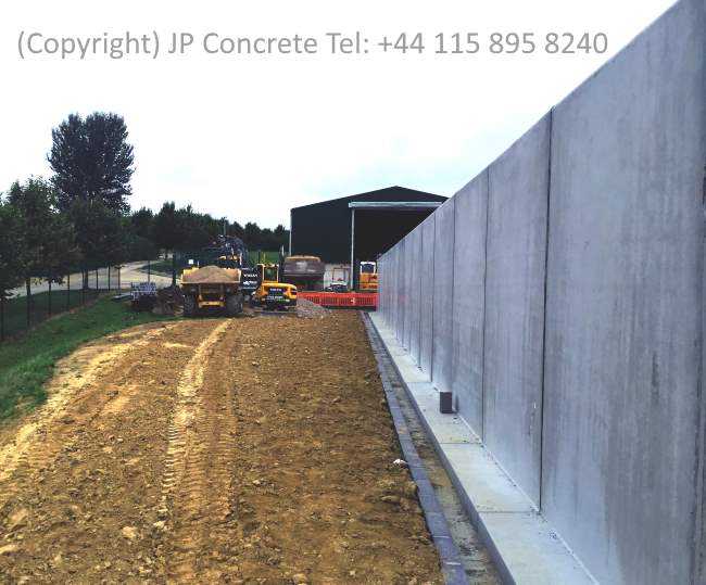
Source: JP Concrete.
Historical Development of Heavy-Duty Precast Silage Clamp Walls
The original 2018 article also discussed the development of heavier-duty prestressed concrete panels for large agricultural and anaerobic digestion silage clamps.
It described how conventional retaining-wall arrangements were being adapted to meet the demands of larger compaction machines and greater stored crop quantities.
One historical example concerned ACP (Concrete) Ltd and a reported 280 mm prestressed panel arrangement intended for high-load silage clamp applications.
This was an example of a supplier response to changing machinery and storage requirements, rather than evidence that any particular panel thickness is universally appropriate.
The correct design response is to determine the loading and specify an engineered wall system accordingly.
Designers should request documented load ratings, design assumptions, foundation requirements, connection details and relevant certification from suppliers.
Silage Sheets, Wall Linings and Airtight Sealing
Although this article focuses on structural construction, the design should allow the stored silage to be effectively covered and sealed.
Suitable impermeable top sheets, side-wall linings and weighting systems help restrict air entry and water infiltration.
Wall joints and surface defects can create pathways for air or moisture, affecting silage quality as well as structural durability.
The original article referred to specialist silage side sheets supplied by Kelvin Cave Ltd. These remain an example of the type of consumable product that may be considered when planning a complete silage storage system.
Current product dimensions, thicknesses and suitability should be confirmed with the supplier rather than relying on 2018 specifications.
Good clamp construction supports effective silage preservation, but long-term silage quality also depends on harvesting, consolidation, covering and feed-out practices.
Silage Clamp Inspection and Maintenance
Silage clamps should be inspected regularly, particularly before filling and after emptying.
A practical inspection programme should include:
- Cracking, spalling or chemical attack of concrete surfaces.
- Damage or displacement of wall panels.
- Loose or deteriorating connections.
- Failed construction joints and sealants.
- Settlement or cracking of the base.
- Blocked or damaged effluent drainage channels.
- Leakage from effluent tanks and connecting pipework.
- Deterioration of asphalt or other impermeable surfacing.
- Damage from loading machinery.
- Evidence of contaminated water leaving the site.
Defects should be assessed according to their significance.
Minor maintenance may be straightforward, but structural cracks, panel movement, major settlement or suspected loss of containment should be referred to appropriately qualified specialists.
Repairs must use materials suitable for the chemical exposure and operating environment.
What Affects Silage Clamp Construction Costs?
The total cost of building a silage clamp depends on considerably more than the price of concrete wall panels.
Important cost elements include:
- Site clearance and earthworks.
- Ground investigation and foundation construction.
- Concrete or asphalt base construction.
- Precast or cast-in-situ walling.
- Retaining-wall connections and restraints.
- Drainage channels, pipes and effluent tanks.
- Clean-water diversion arrangements.
- Access roads, manoeuvring areas and site safety provisions.
- Design, planning and regulatory compliance.
- Construction quality assurance and commissioning.
- Future inspection and maintenance.
Vertical-wall designs may reduce land take but require substantial engineered retaining structures. Sloping-wall designs may offer earthworks advantages where appropriate ground conditions and space are available.
Comparisons should therefore consider total installed cost and expected whole-life performance rather than simply price per linear metre of wall.
Common Silage Clamp Design Mistakes
The following errors can undermine otherwise promising projects:
- Underestimating structural loads: Choosing walls without considering the actual compaction machinery and maximum storage height.
- Insufficient effluent capacity: Sizing the tank only to the regulatory minimum without assessing peak contaminated water flows.
- Ignoring ground conditions: Failing to investigate bearing capacity, settlement and groundwater.
- Inadequate drainage details: Allowing contaminated liquid to escape through joints or unsuitable outfalls.
- Poor separation of clean and dirty water: Creating excessive contaminated runoff or unintended pollution pathways.
- Using inappropriate materials: Failing to consider the chemical aggressiveness of silage effluent.
- Insufficient operational space: Designing storage capacity without suitable access, loading and feed-out arrangements.
- Assuming planning permission is unnecessary: Failing to check the particular development’s planning status.
- Leaving maintenance until failure occurs: Allowing small defects to develop into structural or pollution problems.

Frequently Asked Questions About Silage Clamps
What is a silage clamp?
A silage clamp is a storage facility used to preserve chopped forage crops under oxygen-limited conditions. It may be constructed as a flat pad, a vertical-wall bunker or a sloping-wall arrangement.
Do silage clamps need planning permission?
Planning requirements depend on the proposed use, development dimensions, agricultural permitted development rights, location and site circumstances. Operators should check with their local planning authority before construction. Separate environmental notification requirements may also apply.
What regulations apply to silage clamps in England?
The principal silage storage pollution-control requirements are contained in the SSAFO Regulations. They include provisions concerning impermeable construction, effluent collection, siting, notification and maintenance. Additional planning and other regulatory requirements may apply.
How much notice must be given before building a silage clamp?
In England, the Environment Agency must normally be notified at least 14 days before construction of new silage storage or substantial alterations to an existing installation.
What is the difference between a vertical-wall and sloping-wall silage clamp?
Vertical walls generally make more efficient use of land but require substantial structural resistance to stored silage and compaction loads. Sloping walls may offer operational or earthworks advantages but generally require a larger footprint.
How much silage can a clamp hold?
Capacity depends on internal dimensions, usable height, the shape of the stored silage and its compacted bulk density. A reliable estimate requires a suitable density assumption and a realistic assessment of the clamp geometry.
Does a silage clamp need an effluent tank?
Regulated silage silos in England must have an appropriate effluent collection and containment system. Tank capacity must satisfy the applicable minimum requirements and be adequate for expected effluent production and contaminated water flows.
Why is silage effluent dangerous?
Silage effluent can have a very high organic pollution load. If it reaches a watercourse, microorganisms breaking down the material may rapidly consume dissolved oxygen, harming fish and other aquatic organisms.
Can an old silage clamp continue to be used?
Some older installations may qualify for transitional exemptions, but they must not cause pollution. Substantial alteration may trigger newer construction requirements, and environmental regulators can require improvements where significant pollution risks exist.
What is the best concrete for a silage clamp?
There is no universal concrete mix suitable for every clamp. Concrete specification must take account of structural loads, chemical exposure, permeability, abrasion, joints, reinforcement durability and construction conditions. A qualified engineer should specify the complete system.
Are silage clamps suitable for anaerobic digestion plants?
Yes. Silage clamps are widely used to store agricultural feedstocks for anaerobic digestion. Their capacity, structural loading, drainage and operational arrangements should be matched to the proposed feedstock and AD plant requirements.
Conclusion: Good Silage Clamp Design Protects Both Feedstock and the Environment
A properly designed silage clamp is a critical piece of agricultural and anaerobic digestion infrastructure.
The best design will not necessarily be the cheapest structure to build. It will be the arrangement that provides safe storage, suitable compaction and feed-out conditions, effective effluent containment and satisfactory performance over its intended service life.
Farmers and AD developers should give particular attention to structural loading, ground conditions, impermeability, drainage and environmental requirements before selecting a construction system.
Choosing the right clamp arrangement at the design stage can prevent years of operational difficulties and potentially serious pollution liabilities.
Further Reading
- Biogas Silage Management Techniques and Optimisation Strategies – preserving feedstock quality and biogas potential.
- Anaerobic Digestion Technology – technologies used in AD facilities.
- Anaerobic Digestion Costs – understanding development expenditure.
Technical and Regulatory References
- Environment Agency: Storing Silage, Slurry and Agricultural Fuel Oil. Updated 26 January 2026.
- Environment Agency: Notification of New or Substantially Altered Storage.
- The Water Resources (Control of Pollution) (Silage, Slurry and Agricultural Fuel Oil) (England) Regulations 2010.
- Welsh Government: Cross Compliance – Water Protection 2026.
- BS 5502-22:2003+A1:2013 – Buildings and Structures for Agriculture: Code of Practice for Design, Construction and Loading.
Originally published 23 November 2018. Substantially revised October 2026 to update design guidance, structural engineering considerations, silage effluent containment and regulatory information. Historical supplier and construction case studies have been retained and distinguished from current recommendations.
By Steve Last, MICE, MCIWM, CEnv – IPPTS Associates. Chartered Civil and Environmental Engineer, Chartered Waste Manager and Chartered Environmentalist.





How do you get a farmer to stop these clamps smelling. Do they have to be so awful?
Fantastic! I wish to know what is the concrete mix spec you advise, where do you buy the asphalt? Spec for it? I am a tiny bit acquainted with these requirements and your article gave me a bright idea.
There’s too many cattle on so many Welsh Farms. Hay sheds have been replaced with silage clamps and sand has taken the place of straw as bedding. Gone are the middens where manure would slowly decompose before being spread on the fields in late winter and early spring to nourish the first flush of new growth. In their place we see enormous lagoons filled with a noxious, nutrient rich, highly mobile, slurry which is produced in such quantities that regular disposal through spreading is required, regardless of conditions or the benefit or otherwise to the land.
It’s killing our rivers. We cannot allow the devastating effects of intensive dairy practices on our rivers to be ignored any longer.