




Successful anaerobic digestion plant design begins with the feedstock, not with a digester tank selected from a catalogue.
The quantity, composition and variability of the material entering the plant determine the digestion process, reactor volume, feeding system, mixing duty, heating demand, biogas production, digestate output and much of the civil engineering.
An AD plant must therefore be designed as one integrated biological, mechanical, electrical and civil engineering system.
This guide explains how commercial anaerobic digesters and biogas plants are designed, which information is needed before sizing begins, and why process design and civil engineering design must be developed together.
It is intended as an educational introduction rather than a substitute for site-specific engineering. Final designs should be prepared and checked by suitably qualified professionals working to the legislation, technical standards and approval requirements applicable at the project location.
Key Takeaways – Anaerobic Digestion Plant Design
- The feedstock design basis controls the whole plant. Reliable information is needed about quantity, total solids, volatile solids, contaminants, biochemical methane potential and seasonal variation.
- Process, mechanical, electrical, instrumentation, control, civil and structural design are separate but closely connected disciplines.
- Reliable instrumentation provides the operating data needed by the SCADA system, plant operators and any smart process-control systems.
- Digester volume should be checked against both hydraulic retention time and organic loading rate.
- A design must cover the complete material flow from reception through digestion to biogas use and digestate storage.
- Drawings, mass balances and equipment schedules must describe the same plant.
- Accessibility, maintainability, redundancy and safe shutdown arrangements should be considered before construction.
- Environmental permitting, planning, gas safety and digestate requirements vary between countries and jurisdictions.
- There is no universally best digester design. The appropriate solution depends on the feedstock, project objectives, site and available infrastructure.
What Is Anaerobic Digestion Plant Design?
Anaerobic digestion plant design is the coordinated process of turning a project objective and a supply of organic material into a safe, operable and economically viable treatment facility.
The design must answer several fundamental questions:
- What materials will the plant receive?
- How much will arrive each day and throughout the year?
- What contaminants will be present?
- Which digestion process is suitable?
- How large should the digester be?
- How will the material be received, prepared, pumped and mixed?
- How much biogas and digestate may be produced?
- How will the biogas be stored, treated and used?
- Where will the digestate go?
- What happens when an important machine is unavailable?
- How will tanks, roads, drainage, foundations and containment be constructed?
- How will the plant be operated and maintained safely?
A technically impressive digester is not a successful plant if feedstock cannot reach it reliably, digestate cannot leave the site, the gas user is frequently unavailable or essential equipment cannot be maintained.
AD Plant Design Requires Several Engineering Disciplines
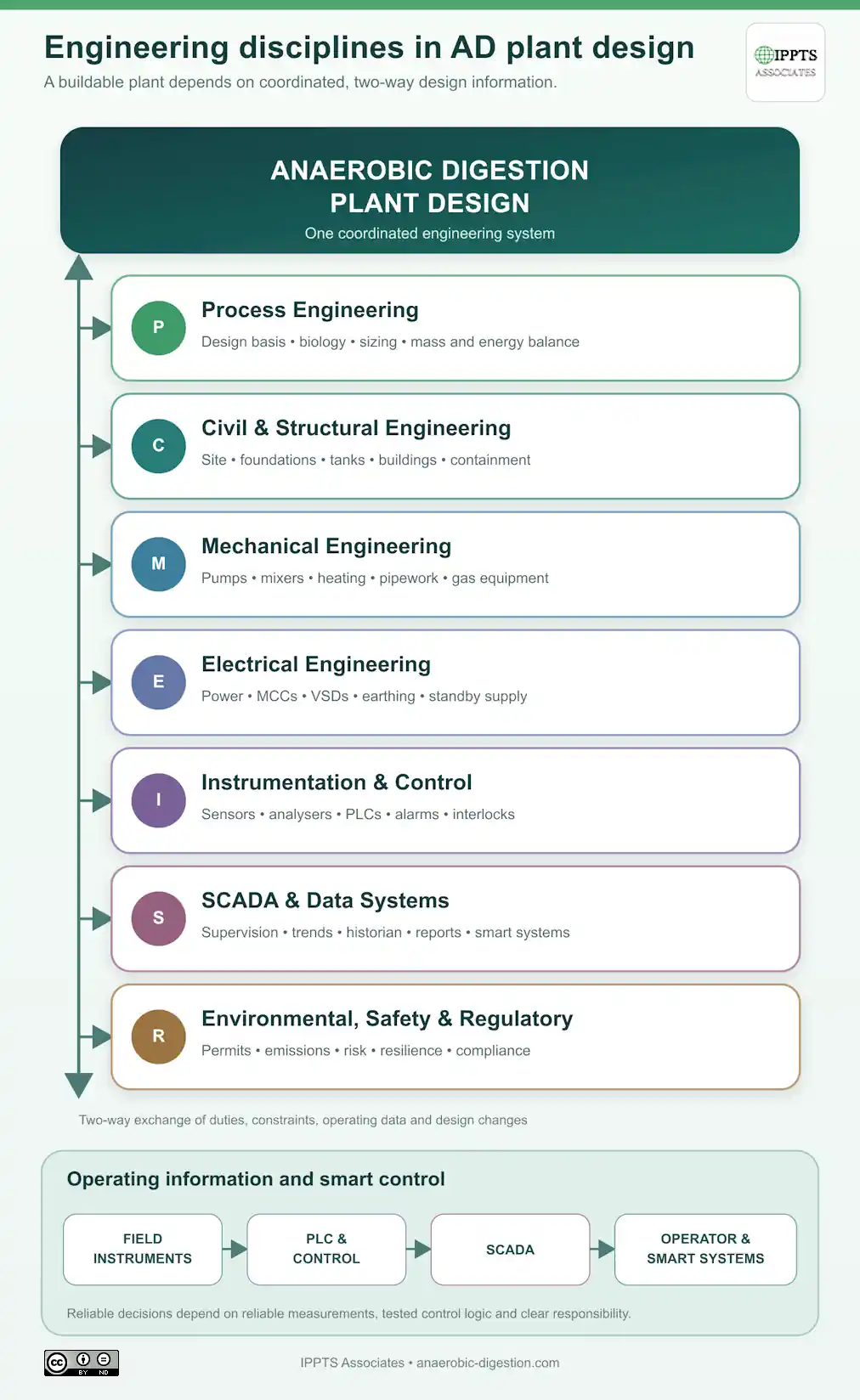
The expression “anaerobic digestion plant design” is sometimes used as though it describes one activity. In practice, a safe and buildable AD plant requires several coordinated engineering disciplines.
These normally include:
- anaerobic digestion process design;
- mechanical design;
- electrical design;
- instrumentation, control and automation;
- SCADA system design;
- civil and structural engineering; and
- environmental, safety and regulatory design.
No discipline can be completed properly in isolation. A change in one part of the design will frequently affect several others.
Anaerobic Digestion Process Design
Process design defines how the feedstock will be converted into biogas and digestate. It establishes the biological and material basis on which the rest of the plant is designed.
Process design commonly includes:
- feedstock characterisation;
- biochemical methane potential assessment;
- material and energy balances;
- digestion technology selection;
- hydraulic and solids retention times;
- organic loading rate;
- digester working volume;
- feed preparation and dosing requirements;
- mixing and heating duties;
- expected biogas production and composition;
- gas treatment and utilisation requirements;
- digestate separation, treatment and storage;
- process operating limits; and
- commissioning and biological start-up requirements.
The process designer should produce clear design criteria, process-flow diagrams, mass and energy balances, equipment duties, operating descriptions and control requirements.
Mechanical Design
Mechanical design converts the process requirements into equipment and pipework capable of performing the required duties.
It may include:
- feed hoppers and reception systems;
- depackaging, screening and contaminant removal;
- pumps and pumping systems;
- digester mixers;
- heat exchangers and heating circuits;
- blowers, compressors and gas boosters;
- gas holders and pressure-control equipment;
- gas cleaning and upgrading equipment;
- digestate separators;
- pipework, valves and supports;
- equipment materials and corrosion protection;
- hydraulic calculations;
- pressure-loss calculations;
- equipment access and lifting arrangements; and
- maintenance, isolation and replacement requirements.
Mechanical equipment must be selected for the real properties of the feedstock. Pumps and valves that work reliably with clean water may perform poorly with fibrous, abrasive or gas-entrained organic slurry.
The mechanical designer must also consider how blocked equipment will be isolated and cleared, whether mixers can be removed without emptying a digester, and how large components will eventually be replaced.
Electrical Design
Electrical design provides the power, protection and distribution systems needed to operate the plant safely and reliably.
Electrical design may include:
- the plant electrical-load schedule;
- incoming electrical supply;
- transformers and switchgear;
- motor-control centres;
- variable-speed drives;
- cable sizing and containment;
- equipment isolation;
- earthing and bonding;
- lightning protection;
- lighting and small-power systems;
- standby generation;
- uninterruptible power supplies;
- electrical metering;
- hazardous-area equipment selection;
- emergency shutdown and safety circuits; and
- capacity for future plant expansion.
An electrical-load schedule should distinguish between normal operating loads, intermittent loads, starting loads and equipment that must remain available during a power failure.
Critical equipment may include control systems, gas-holder protection, emergency lighting, ventilation, gas detection, pressure protection and equipment needed to place the plant into a safe condition.
Instrumentation, Control and Automation Design
Instrumentation provides the measurements needed to understand what is happening within the plant.
Control systems use those measurements to start, stop and regulate equipment. They may maintain tank levels, control feed rates, adjust temperature, operate mixers, route biogas and respond to abnormal conditions.
Instrumentation and control design may include:
- the instrument schedule;
- instrument specifications and measurement ranges;
- control-valve selection;
- input and output schedules;
- control philosophies;
- cause-and-effect schedules;
- alarm and trip settings;
- programmable logic controllers;
- communications networks;
- local control panels;
- operator interfaces;
- data storage and reporting;
- functional testing; and
- integration of equipment supplied by different manufacturers.
A control system is only as dependable as the instruments supplying its data. Incorrectly selected, badly positioned or poorly maintained instruments can produce misleading information and inappropriate automatic responses.
SCADA Design
SCADA stands for Supervisory Control and Data Acquisition.
A SCADA system brings plant information together and presents it to the operator. It commonly displays process conditions, equipment status, trends, alarms, operating totals and historical records.
SCADA may allow an authorised operator to:
- see the current condition of the plant;
- start or stop permitted equipment;
- change approved operating setpoints;
- acknowledge and investigate alarms;
- compare current and historical performance;
- identify developing mechanical or biological problems;
- produce environmental and production reports; and
- review energy production and consumption.
The SCADA system usually receives data through programmable logic controllers and remote input/output equipment connected to field instruments.
SCADA should not be confused with the instruments themselves. The instruments measure the plant. The control system processes those measurements and issues commands. SCADA provides supervision, visualisation, data acquisition and operator interaction.
Smart Process-Control Systems
Reliable SCADA data can also support more advanced or smart control systems.
Depending on the plant, smart systems may help to:
- adjust feed rates in response to biological loading;
- adjust dosing rates;
- optimise mixer operating cycles;
- reduce parasitic electricity consumption;
- manage digester heating;
- predict equipment-maintenance requirements;
- identify abnormal gas composition;
- coordinate biogas production with gas use or storage;
- optimise biomethane-upgrading operation; and
- identify gradual departures from normal plant performance.
Automation should not conceal an inadequately understood process. Smart systems need defined operating limits, dependable input data, transparent decision rules, appropriate alarm handling and the ability for trained operators to intervene.
Civil and Structural Engineering Design
Civil and structural engineering turns the process, mechanical and electrical concept into physical infrastructure.
It may include:
- topographical and geotechnical investigations;
- site levels and earthworks;
- access roads and vehicle movements;
- tank bases and structural foundations;
- buildings and equipment slabs;
- secondary containment and bunding;
- clean-water and dirty-water drainage;
- underground services and pipe corridors;
- retaining structures;
- delivery and loading areas;
- fire-service access;
- durability, waterproofing and corrosion protection; and
- construction sequencing and temporary works.
Engineering Interfaces Must Be Managed
A change in digester volume may alter structural loading, mixing power, heating demand, cable sizes and instrument ranges. Integrating the multiple requirements of an anaerobic digestion plant design can be onerous, especially when client requirements change during the design process.
Moving a reception building may change road geometry, pumping distances, electrical distribution, odour extraction and drainage.
Selecting a larger motor may affect the mechanical drive, electrical-load schedule, motor-control centre, variable-speed drive, cable size, standby-power requirement and SCADA configuration.
Interface management is therefore one of the most important parts of AD plant design. Process-flow diagrams, piping and instrumentation diagrams, equipment schedules, electrical-load schedules, instrument lists, control descriptions and civil drawings should all describe the same plant.
Engineering disciplines involved in AD plant design:
Anaerobic Digestion Process Design
Process design defines how the feedstock will be converted into biogas and digestate. It commonly includes:
- feedstock characterisation;
- biochemical methane potential assessment;
- material and energy balances;
- digestion technology selection;
- hydraulic and solids retention time;
- organic loading rate;
- digester working volume;
- feed preparation and dosing;
- mixing and heating requirements;
- biogas production and composition;
- gas cleaning and utilisation;
- digestate separation, storage and treatment;
- process instrumentation and control; and
- commissioning and biological start-up.
Anaerobic Digestion Civil Engineering Design
Civil and structural design turns the process concept into physical infrastructure. It may include:
- topographical and geotechnical investigations;
- site levels and earthworks;
- access roads and vehicle movements;
- tank bases and structural foundations;
- buildings and equipment slabs;
- secondary containment and bunding;
- clean-water and dirty-water drainage;
- underground services and pipe corridors;
- retaining structures;
- delivery and loading areas;
- fire-service access;
- durability, waterproofing and corrosion protection; and
- construction sequencing and temporary works.
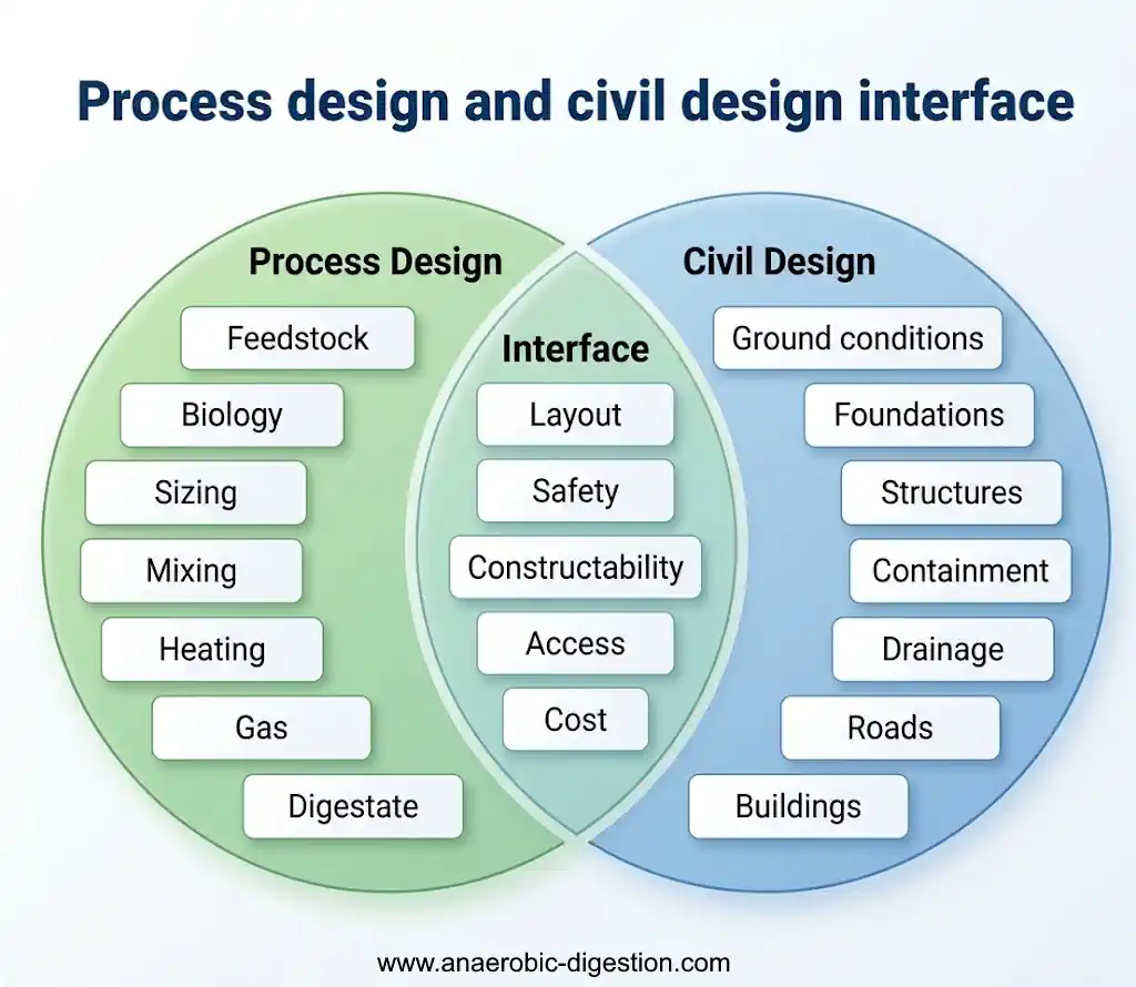
Process design and civil design interface:
Step 1: Define the Purpose of the AD Plant
The design team must first establish what the project is intended to achieve.
Possible primary objectives include:
- treating food waste or other biodegradable wastes;
- stabilising sewage sludge;
- treating industrial wastewater;
- managing livestock manure and agricultural residues;
- producing renewable electricity and heat;
- producing biomethane for a gas network or vehicle fuel;
- reducing methane emissions from existing waste-management practices;
- producing a useful digestate fertiliser; or
- integrating renewable gas production with an industrial facility.
A plant designed primarily to treat high-strength industrial wastewater will differ greatly from a farm digester processing manure, even though both employ anaerobic microorganisms.
The plant objective should be written as a measurable design brief. It should state the required throughput, expected availability, product requirements, operating philosophy, design life and known regulatory constraints.
Step 2: Establish the Feedstock Design Basis
Feedstock information is the foundation of the design.
A useful design basis should address:
- daily and annual tonnage or volume;
- minimum, average and peak delivery rates;
- total solids and moisture content;
- volatile solids or chemical oxygen demand;
- particle size and physical form;
- viscosity and pumpability;
- biochemical methane potential;
- carbon-to-nitrogen balance;
- potential ammonia, sulphide or salt inhibition;
- pH and alkalinity;
- sand, grit and dense solids;
- plastics, metals, glass and other contaminants;
- pathogen-control requirements;
- seasonal variation; and
- the security and duration of the feedstock supply.
A single laboratory result should not automatically be treated as representative of several years of operation. Samples need to reflect the actual range of materials, suppliers and seasons that the plant may experience.
Designers should also investigate how the feedstock may change over the plant’s life. A system optimised around one narrow substrate specification may become difficult to operate if commercial or agricultural circumstances change.
Step 3: Prepare the Mass and Energy Balances
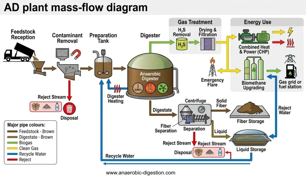
A process mass balance tracks material through the complete plant.
It should account for:
- feedstock entering the site;
- added dilution or process water;
- removed packaging and contaminants;
- material sent to digestion;
- biogas production;
- digestate production;
- separated liquid and fibre;
- recirculated process streams;
- wash water and contaminated drainage; and
- other rejects and residues.
The energy balance should consider:
- the chemical energy available in the biogas;
- heat required to warm incoming feedstock;
- digester heat loss;
- mixing and pumping energy;
- feedstock-preparation energy;
- gas-cleaning and upgrading demand;
- digestate-processing demand;
- auxiliary power during normal operation; and
- critical power needed during an outage.
Gross gas production is not the same as exportable energy. Parasitic electrical and heat demands should be deducted when estimating the useful output of the plant.
AD plant mass-flow diagram:
Step 4: Select the Digestion Process
Technology selection should follow the design basis rather than precede it.
Wet and Dry Digestion
Wet digestion treats a pumpable feed mixture. It is widely used for manure, sewage sludge, food-waste slurry and many industrial residues.
Dry or high-solids digestion treats stackable or much less pumpable materials. Systems may operate continuously or as batches within tunnel-like reactors.
The labels “wet” and “dry” can obscure important differences between technologies. Designers should state the actual solids range and rheological assumptions rather than relying on the category name alone.
High-Solids and Low-Solids Wet Digesters
Wet digesters may process relatively dilute liquids or much thicker slurries.
A higher-solids wet digester may reduce the liquid volume that must be contained and can therefore reduce the reactor volume and land needed for an equivalent mass of dry feed. However, thicker material can require more energy for pumping and mixing and can increase wear, blockage and heat-transfer problems.
A lower-solids mixture is usually easier to pump and mix, but dilution water increases the volume requiring heating, digestion, storage and eventual management.
This relationship between solids content, volume and land requirement has long been recognised in descriptions of anaerobic digester configuration and remains an important design consideration.
Batch and Continuous Digestion
In a batch system, feedstock is placed in a reactor and remains there for a defined digestion period. Several reactors may operate at different stages to produce a more consistent combined gas flow.
Continuous systems receive and discharge material regularly. They can provide relatively stable gas production but require dependable feeding, pumping, mixing and process control.
Continuously Stirred Tank Reactors
Continuously stirred tank reactors, usually abbreviated to CSTRs, are common for pumpable feedstocks. They rely on effective mixing to distribute incoming material, heat and microorganisms.
Theoretical tank volume alone does not guarantee effective retention. Short-circuiting, dead zones, foam, floating layers and accumulated grit can all reduce useful working volume.
Plug-Flow Digesters
Plug-flow systems are intended to move material through the reactor with less longitudinal mixing than a CSTR. They can suit thicker, more consistent feedstocks, but their performance depends strongly on rheology and feed preparation.
High-Rate Wastewater Reactors
Industrial wastewater may be treated in reactors such as upflow anaerobic sludge blanket, expanded granular sludge bed or internal-circulation systems.
These systems can retain microbial solids while allowing liquid to pass through much more quickly. Consequently, hydraulic retention time and solids retention time may be very different. They require specialist wastewater characterisation and reactor design and should not be sized using simple farm-digester assumptions.
Step 5: Calculate the Required Digester Volume
Preliminary sizing commonly includes two fundamental checks:
- hydraulic retention time; and
- organic loading rate.
Hydraulic Retention Time Check
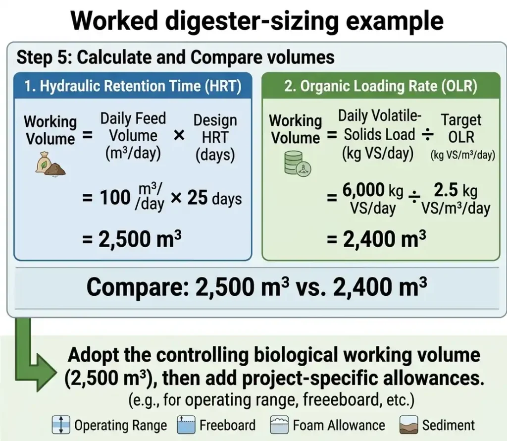
For a simple completely mixed system:
Working volume = daily feed volume × design hydraulic retention time
If a plant receives 100 cubic metres of prepared feed each day and the selected design retention time is 25 days:
100 m³/day × 25 days = 2,500 m³ working volume
Organic Loading Rate Check
The organic loading check may be expressed as:
Required working volume = daily volatile-solids load ÷ target organic loading rate
If the prepared feed contains 6,000 kilograms of volatile solids per day and the selected loading rate is 2.5 kilograms of volatile solids per cubic metre per day:
6,000 kg VS/day ÷ 2.5 kg VS/m³/day = 2,400 m³ working volume
In this simplified example, the retention-time calculation produces the larger result, so the preliminary biological working volume would be at least 2,500 cubic metres.
The final tank capacity would also need to account for matters such as:
- operating level range;
- freeboard;
- foam allowance;
- sediment accumulation;
- inactive or poorly mixed zones;
- feed variability;
- future operating flexibility; and
- the selected tank and gas-holder arrangement.
This example illustrates the method; it is not a universal design loading. Suitable retention times and organic loading rates depend on the feedstock, temperature, reactor type, biological kinetics and operating strategy.
Worked digester-sizing example:
Step 6: Design Feedstock Reception and Pre-Treatment
Reception design should reflect how material actually arrives at the site.
Possible facilities include:
- weighbridges;
- vehicle inspection and sampling areas;
- liquid reception tanks;
- solid-feed hoppers;
- enclosed tipping halls;
- depackaging equipment;
- screens, magnets and grit removal;
- macerators or size-reduction equipment;
- pasteurisation systems; and
- buffer and blending tanks.
Designers should consider peak vehicle arrivals, rejected loads, spills, washdown, odour extraction and what happens when a reception system is unavailable.
Unrealistically clean feedstock specifications are a common cause of operational problems. Waste-derived materials may contain packaging, grit, metal, glass and other items capable of damaging downstream equipment.
Step 7: Integrate Pumps, Mixers and Heating
Equipment should be selected using the actual duty rather than nominal clean-water performance.
Pumping
Pump selection should consider:
- flow and required pressure;
- solids content;
- viscosity;
- particle and fibre size;
- abrasiveness;
- gas entrainment;
- maintenance access; and
- the ability to isolate and clear blockages safely.
Mixing
Mixing should provide useful contact between microorganisms and feedstock, distribute heat, limit sedimentation and reduce floating layers.
More installed mixing power does not automatically mean better digestion. The objective is effective mixing with acceptable energy use and maintainable equipment.
Designers should consider whether mixers can be removed without emptying the digester and how accumulated grit will be identified and removed.
Heating
The heat balance should include the energy required to warm incoming feedstock and replace heat lost through tanks, roofs and pipework.
Heat exchangers and recirculation systems should be designed for fouling fluids and should be accessible for cleaning. Stable temperature control is generally more important than continually chasing a theoretical optimum.
Step 8: Design the Biogas System
The gas system connects production within the digester to safe storage, treatment and utilisation.
It may include:
- gas collection pipework;
- condensate removal;
- low- and high-pressure protection;
- gas storage;
- hydrogen sulphide removal;
- drying and filtration;
- siloxane treatment where required;
- gas boosters or compressors;
- combined heat and power engines;
- boilers;
- biomethane upgrading;
- grid-injection equipment;
- carbon-dioxide treatment; and
- an emergency or standby flare.
Gas-storage capacity should be designed around realistic fluctuations in production and consumption. It is usually a short-term buffer rather than long-duration energy storage.
The gas-treatment specification should be based on the requirements of the downstream user. An engine, boiler, upgrading system and gas network may each impose different limits.
Step 9: Plan Digestate Handling Before Finalising the Digester
Digestate is a major output, not a minor residue.
The design should define:
- whether digestate remains whole or is separated;
- liquid and fibre quantities;
- storage duration;
- seasonal restrictions on land application;
- transport and loading arrangements;
- nutrient content;
- quality requirements;
- rainfall entering storage areas;
- odour control; and
- alternative outlets if the preferred destination is unavailable.
A plant can be constrained by digestate storage before it is constrained by digester capacity. Storage and off-take assumptions must therefore be tested as carefully as biogas assumptions.
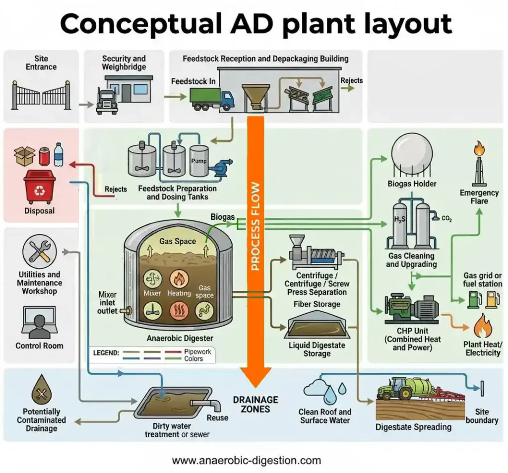
AD Plant Layout and Civil Engineering
A good layout supports safe traffic movement, short process connections, logical drainage, maintenance access and future expansion.
Important layout relationships include:
- delivery vehicles and reception points;
- clean and dirty operational areas;
- feed tanks and digester pumping distances;
- gas equipment and potential ignition sources;
- digestate loading and storage;
- odour-sensitive receptors;
- emergency access and escape routes;
- crane and lifting access;
- underground services;
- control rooms and occupied buildings; and
- space for future replacement or expansion.
Conceptual AD plant layout:
Ground Investigation and Foundations
Large digesters impose substantial loads and can be sensitive to differential settlement.
A geotechnical investigation may need to establish:
- soil strength and compressibility;
- groundwater conditions;
- contamination;
- made ground or buried obstructions;
- chemical attack on concrete;
- flood risk;
- slope stability; and
- appropriate foundation options.
Foundation solutions must be developed from site-specific structural loads and ground conditions. Generic slab thicknesses copied from another project are not a safe substitute for engineering design.
Containment and Drainage
The civil design should prevent loss of feedstock, digestate, contaminated water and process chemicals to the environment.
It should distinguish between:
- clean roof and surface water;
- potentially contaminated yard drainage;
- process drainage;
- tank overflows;
- firewater; and
- exceptional spill or tank-failure scenarios.
Secondary containment must include valves, connections and pipework interfaces as well as tanks. Designers should consider rainfall accumulation, safe emptying, inspection, joint detailing and the consequences of one containment area overflowing into another.
UK Regulatory Note
This section provides a general signpost for England and should not be treated as project-specific legal advice. Requirements differ across England, Wales, Scotland and Northern Ireland and may change.
AD facilities may require planning permission, environmental permitting and approvals relating to waste, animal by-products, gas systems, electricity generation, grid connection, drainage and digestate use.
The Environment Agency’s biological-waste appropriate-measures guidance covers wet, dry and dry-batch digestion, biogas use or upgrading, digestate treatment and associated storage.
England’s standard-rules environmental permits include different rule sets for larger installations, waste-recovery operations, on-farm plants and wastewater-treatment sludge digestion. Several AD rule sets were updated on 26 February 2026.
The applicable permit may impose requirements covering:
- impermeable surfaces and secondary containment;
- clean- and dirty-water drainage;
- covered digestate storage;
- odour control;
- gas storage and treatment;
- standby flaring;
- monitoring and alarms;
- leak detection and repair;
- commissioning plans; and
- inspection and maintenance.
Biogas can create fire, explosion, asphyxiation and toxic-gas hazards. The UK Health and Safety Executive explains that the Dangerous Substances and Explosive Atmospheres Regulations require workplace fire and explosion risks to be assessed and reduced as far as reasonably practicable.
Permitting and safety requirements should influence the layout from the beginning. They should not be added after the main equipment arrangement has already been fixed.
Design for Safety, Maintenance and Failure
AD plants contain moving machinery, confined spaces, pressure systems, flammable gas and potentially toxic hydrogen sulphide.
The design process should examine:
- gas detection and ventilation;
- hazardous-area classification;
- pressure and vacuum protection;
- safe isolation;
- confined-space access;
- overfilling;
- foam and blockage scenarios;
- electrical failure;
- loss of heat or mixing;
- failure of the CHP engine or upgrading plant;
- flare availability;
- emergency power;
- chemical handling;
- vehicle and pedestrian segregation; and
- emergency response.
Every critical item should have a defined failure response. This does not mean duplicating every machine. It means understanding the consequence of failure and providing an appropriate combination of redundancy, stored capacity, alternative operation, spares and repair access.
Instrumentation, Automation and SCADA
An AD plant cannot be controlled reliably without dependable information about its biological, mechanical and electrical condition.
Instrumentation collects that information. The control system uses it to regulate the process. SCADA presents the information to the operator and stores it for analysis, reporting and future optimisation.
Field Instrumentation
Depending on the plant, field instruments may measure:
- feedstock mass and flow;
- liquid and slurry flow;
- tank and vessel level;
- pressure and vacuum;
- digester and pipework temperature;
- pH;
- gas flow;
- methane concentration;
- carbon-dioxide concentration;
- oxygen concentration;
- hydrogen-sulphide concentration;
- electrical power and energy consumption;
- motor current;
- pump, mixer and valve status;
- equipment vibration or temperature;
- gas detection within buildings or enclosed areas;
- emissions and flare operation; and
- selected digestate-quality parameters.
Some important biological measurements may still depend on laboratory testing rather than continuous online instruments. These can include volatile fatty acids, alkalinity, ammonia, total solids and volatile solids.
Laboratory results should be incorporated into the operating-data system where practical so that biological trends can be compared with feed rates, temperature, gas production and other continuously recorded information.
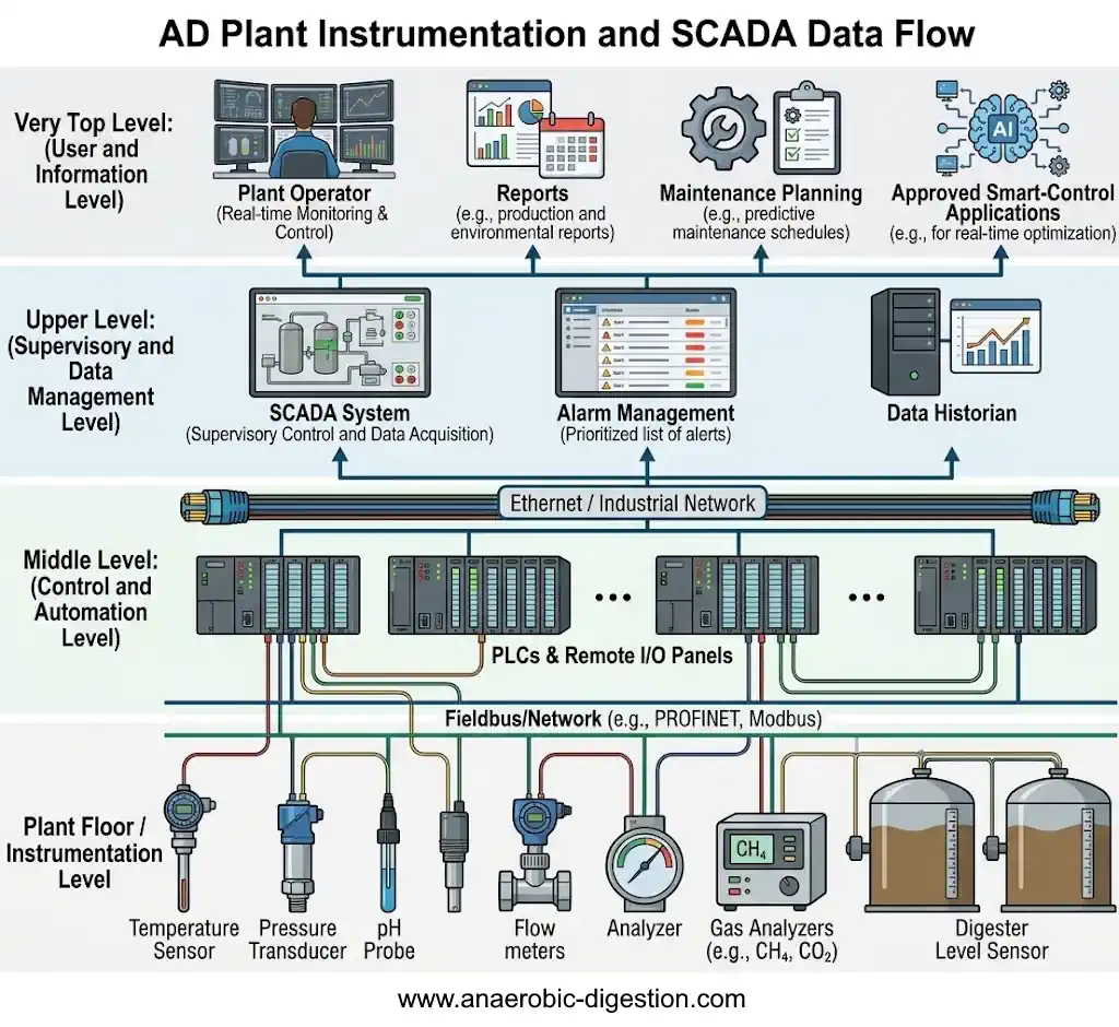
From Instrument to Operator
A typical information path is:
Field instrument → input/output system → programmable logic controller → SCADA → data historian and reports → plant operator or smart control system
Each part of this chain must be designed and tested.
- Field instruments measure the physical or chemical condition.
- Input and output equipment transfers signals between the plant and control system.
- Programmable logic controllers run the automatic control sequences.
- SCADA provides supervision, graphics, alarms, trends and operator controls.
- The data historian retains time-based operating information.
- Reporting tools convert recorded data into useful production, environmental and maintenance information.
- Smart systems may analyse the data and recommend or implement controlled operating changes.
AD plant instrumentation and SCADA data flow:
What the SCADA System Should Show
The SCADA interface should help the operator understand the plant quickly.
Useful displays may include:
- a whole-plant overview;
- feed reception and dosing;
- digester levels, temperatures and pressures;
- pump and mixer status;
- heating circuits;
- gas production, storage and quality;
- CHP or upgrading performance;
- flare status;
- digestate handling;
- electrical demand and generation;
- current alarms;
- historical trends; and
- maintenance or instrument warnings.
Graphics should use consistent symbols, colours and equipment names. Important abnormal conditions should stand out without filling every display with unnecessary animation or colour.
Alarm Management
An alarm should identify a condition requiring a defined operator response.
Poorly designed plants may generate hundreds of repetitive alarms during one fault. This alarm flooding can hide the event that first caused the problem.
An alarm-management philosophy should define:
- which conditions require alarms;
- alarm priorities;
- operator response times;
- deadbands and delay periods;
- how repeated or consequential alarms are handled;
- when alarms may be suppressed;
- how alarm settings are authorised and changed; and
- how alarm performance is reviewed.
Safety-related trips should follow the project’s risk assessment. Critical protection should not depend solely on an ordinary SCADA display or a single communications connection.
Data Quality and Instrument Maintenance
Large quantities of data are not useful if the underlying measurements are inaccurate.
The instrumentation strategy should address:
- measurement range and accuracy;
- instrument location;
- access for inspection and calibration;
- resistance to fouling and corrosion;
- sample conditioning;
- calibration frequency;
- validation against laboratory or manual measurements;
- identification of failed or unreliable signals;
- replacement instruments and spare parts; and
- responsibility for maintaining each instrument.
The SCADA system should distinguish a real zero from a failed, disconnected or out-of-range instrument. A bad signal must not silently become a believable operating value.
Smart Control and Real-Time Optimisation
Once reliable data is available, smart systems can support real-time operating decisions.
Potential applications include:
- feed-rate optimisation;
- early identification of biological instability;
- predictive maintenance;
- adaptive mixer scheduling;
- heat-demand optimisation;
- gas-storage management;
- coordination with electricity prices or gas-grid requirements;
- methane-loss detection; and
- comparison of actual performance with the process design model.
Smart control should be introduced within a defined operating envelope. The system should explain or record important control actions, respect equipment and biological limits, and allow authorised operators to intervene.
A smart system should also fail safely if it loses an instrument signal, communications connection or external data source.
Control-System Cybersecurity
Remote access and connected control systems create cybersecurity risks as well as operational benefits.
The design should consider:
- separation of operational and general business networks;
- user permissions;
- secure remote access;
- software and configuration backups;
- management of updates;
- logging of operator and configuration changes;
- recovery following equipment failure or cyber incident;
- control-system supplier access; and
- how the plant will operate safely if external communications are lost.
Cybersecurity responsibilities should be agreed between the owner, operator, SCADA integrator, equipment suppliers and information-technology providers.
Define Responsibility for System Integration
SCADA integration often crosses several supply contracts.
A mechanical package supplier may provide instruments and a local control panel. An electrical contractor may provide cabling and motor-control equipment. A system integrator may configure the PLC and SCADA. The process designer may define control requirements, while the operator ultimately depends on the completed system.
The project must identify who is responsible for making the whole system work together.
The design documentation should define:
- equipment and instrument tag numbers;
- signal types and communications protocols;
- control ownership;
- equipment operating sequences;
- permissives and interlocks;
- alarm and trip settings;
- data-storage requirements;
- reporting requirements;
- testing responsibilities; and
- final software, passwords, backups and documentation to be handed to the operator.
Commissioning an Anaerobic Digestion Plant
Commissioning is not simply the moment when construction ends.
A comprehensive programme may include:
- civil and structural inspections;
- tank water testing and leak checks;
- pipework testing and cleaning;
- electrical and control-system testing;
- dry testing of motors and safety interlocks;
- instrument calibration;
- gas-system integrity testing;
- testing of alarms and emergency shutdowns;
- verification of mixer performance;
- introduction of inoculum;
- controlled biological loading;
- performance testing; and
- operator training and handover.
Instrumentation, Control and SCADA Commissioning
Control-system commissioning should verify the complete path from each field instrument to the final operator display and controlled item of equipment.
Testing should include:
- instrument calibration and range checks;
- input and output loop checks;
- motor direction and equipment status feedback;
- valve position and fail-position testing;
- control-sequence testing;
- permissive and interlock testing;
- cause-and-effect testing;
- alarm priorities and alarm delays;
- high-high and low-low trip testing;
- emergency shutdown testing;
- communications-failure testing;
- power-failure and restart behaviour;
- standby-power operation;
- historian and reporting checks;
- SCADA user permissions;
- software backup and restoration;
- remote-access security; and
- operator training using realistic fault scenarios.
Factory acceptance testing and site acceptance testing should be planned before commissioning begins. Test records, final software, instrument settings, alarm schedules, network information and restorable backups should form part of the handover documentation.
Biological start-up should follow the rate at which the microbial population adapts. A contractual completion date cannot force an unstable digester to accept its full organic load immediately.
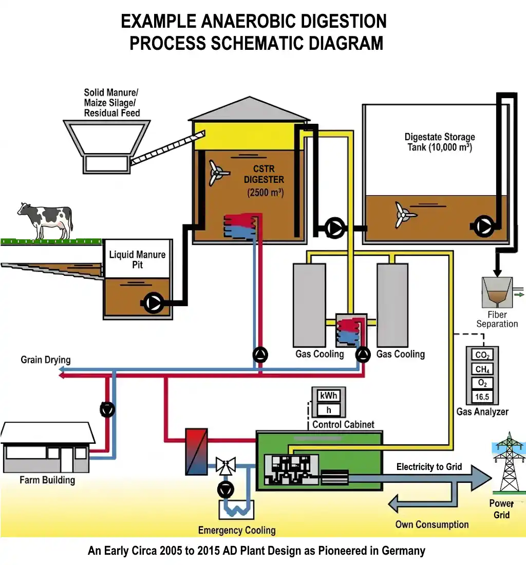
The following historic design data were originally provided:
- Substrates: cattle manure, whole plant corn (maize) crop
- Temperature Range: Mesophilic
- Input: 801 Mg/week (fresh)
- TSS = 6,6 kg/Mg
- VSS = 5,3 kg/Mg
- Reactor volume: 2500 m³
- Detention time: 20 – 30 days
- Volume Load:
- Br = 2,5 kg VSS/m³d
- Yields:
- Electric Power: 40655 kWh/week
- Thermal Power: 55435 kWh/week
Common AD Plant Design Mistakes
- Designing around average feedstock conditions only.
- Using methane-yield figures without representative testing.
- Sizing solely by retention time and ignoring organic loading.
- Ignoring grit, packaging and other contaminants.
- Underestimating pumping, mixing and heating demand.
- Failing to reconcile the mass balance with storage capacity.
- Leaving digestate outlets unresolved.
- Providing inadequate maintenance and lifting access.
- Allowing clean water to enter dirty-water systems unnecessarily.
- Failing to plan for loss of the main gas user.
- Treating the flare as optional.
- Omitting to include for lightning protection.
- Adding containment, drainage and safety provisions too late.
- Commissioning before permits and operating procedures are ready.
A Practical AD Plant Design Checklist
- Has the project objective been defined?
- Are feedstock quantities and characteristics representative?
- Have contaminants and seasonal changes been considered?
- Is there a traceable mass and energy balance?
- Has the technology been selected for the actual feedstock?
- Has volume been checked against both HRT and OLR?
- Can pumps and mixers be maintained safely?
- Are gas production, storage and use balanced?
- Is contingency gas management available?
- Is there adequate digestate storage and a credible outlet?
- Do process, mechanical, electrical and civil drawings agree?
- Are containment and drainage integrated with the layout?
- Have hazardous areas and emergency access been considered?
- Are critical failure responses documented?
- Is commissioning included within the project programme?
Learn More About Anaerobic Digestion Process Design

For a broader introduction to feedstocks, digestion biology, biogas, digestate and successful plant operation, see:
Anaerobic Digestion: A Practical Guide to Feedstocks, Biogas, Digestate and Successful AD PlantsAnaerobic Digestion: A Practical Guide to Feedstocks, Biogas, Digestate and Successful AD Plants
This ebook concentrates primarily on anaerobic digestion process design and operation. It should not be treated as a civil or structural engineering design manual.
Frequently Asked Questions About Anaerobic Digestion Plant Design
What is the first step in anaerobic digester design?
The first step is to establish the plant objective and a reliable feedstock design basis. Digester technology and volume should not be selected until the quantity, composition, variability and contamination level of the feedstock are understood.
How is anaerobic digester volume calculated?
Preliminary volume is commonly checked using hydraulic retention time and organic loading rate. The controlling result is then adjusted for operating levels, freeboard, foam, sediment, inactive zones and project-specific flexibility.
What is the difference between process design and civil design?
Anaerobic digestion plant design, process design defines how feedstock is converted into biogas and digestate. Civil design provides the site infrastructure, foundations, tanks, buildings, roads, drainage and containment needed to construct and operate the process safely.
Is a higher-solids digester always smaller?
Higher solids can reduce the liquid volume needed for a given mass of feedstock. However, thicker material can require more powerful pumping and mixing and may increase abrasion, blockage and heat-transfer problems. The whole system must be evaluated.
What is the best type of anaerobic digester?
There is no universally best type. The correct choice depends on feedstock characteristics, solids content, project scale, required treatment performance, climate, site constraints, available operators and how the biogas and digestate will be used.
Does an anaerobic digestion plant need a flare?
Commercial plants generally need a safe method of managing biogas when normal utilisation equipment is unavailable. The flare and its capacity should be selected from the credible failure and maintenance scenarios applicable to the plant.
Why is civil engineering important to AD plant performance?
Ground movement, poor drainage, inadequate containment, inaccessible equipment and unsuitable vehicle layouts can restrict or damage an otherwise sound process. Civil design directly affects reliability, safety and environmental protection.
Can an AD plant be designed from standard drawings?
Standard details can help, but they cannot replace site-specific design. Feedstock, ground conditions, climate, regulations, equipment, drainage, tank loads and operating requirements vary between projects.
Further Technical Anaerobic Digestion Plant Design Resources
- US EPA AgSTAR Biogas Toolkit
- US EPA Anaerobic Digester/Biogas System Operator Guidebook
- IEA Bioenergy: Implementation of AD Facilities in the Food and Beverage Industry
- Environment Agency: Biological Waste Treatment and Process Control
Professional Anaerobic Digestion Support
If your project requires independent review, feasibility input, process and infrastructure coordination, procurement support or commissioning advice, see our anaerobic digestion consultancy services.
[Published November 2014. Rewritten September 2026.]




Hi there I am so excited I found your blog, I would just like to say kudos for this fantastic post and a all round interesting blog. Would you please provide more information about the rural community biogas in Kenya, and kind people to help us. Website you want is my cousin’s.
Fantastic post, very much useful information for a new starter in anaerobic digestion plant design. It is really a hidden gem. I found your blog a few days ago from a Google search and have been reading it over the past few days.